Page
Configure the virtual machines
With the cluster now prepared, the VMs are now able to be configured to use the clustered storage.
In order to get full benefit from taking this lesson, you need to:
- Have a functioning Windows Active Directory Domain.
- Have completed the steps in Lesson 1.
In this lesson, you will:
- Configure the individual VMs and use the shared, clustered storage inside the guest operating system.
- Validate that the steps taken allow the use of available storage.
Configure the virtual machines
This learning path assumes a functioning Active Directory Domain (AD domain) is available for the Microsoft Windows 2019 (Windows) virtual machines (VM) to join. It is beyond the scope of this learning path to show how to install an Active Directory Domain Controller and the remaining VMs needed for the environment. It is also beyond the scope of this learning path to show how to configure the VMs for their intended roles.
Please see the Microsoft Windows Server documentation and the Red Hat OpenShift Container Platform documentation for information on installing and configuring the Windows VMs.
After the VMs are created and the guest tools are installed within the operating system (OS), the runStrategy for the VMs should be set. This allows the VM to control its power state. Without setting this, the VM cannot power itself off because OpenShift will simply restart it. Please see the OpenShift documentation for more information on runStrategy.
The .spec.running and .spec.runStrategy options are mutually exclusive; they cannot be specified in a VMs YAML file at the same time. The following command removes the .spec.running option and sets the .spec.runStrategy option to RerunOnFailure:
oc patch vm <VMNAME> --type=json -p='[{"op": "remove", "path": "/spec/running"},{"op": "add", "path": "/spec/runStrategy", "value": "RerunOnFailure"}]'Some of the following configurations will either require a VM to be powered off or for it to be restarted from within OpenShift. The guest tools and configuring the runStrategy help do this.
Active Directory (AD) VM
The AD server used in this learning path also acts as a DNS server and a default gateway for the WSFC VMs. Since the AD VM acts as a gateway device, it needs a network interface connected to the Default pod network and another network interface connected to the NAD network that was created. The following YAML was used to create the AD VM used in this learning path:
apiVersion: kubevirt.io/v1
kind: VirtualMachine
metadata:
  name: ad
  namespace: winding
spec:
  dataVolumeTemplates:
  - apiVersion: cdi.kubevirt.io/v1beta1
    kind: DataVolume
    metadata:
      name: ad
    spec:
      source:
        pvc:
          name: w2k19-base-06-12
          namespace: winding
      storage:
        resources:
          requests:
            storage: 60Gi
  runStrategy: RerunOnFailure
  template:
    spec:
      architecture: amd64
      domain:
        cpu:
          cores: 4
          sockets: 1
          threads: 1
        devices:
          disks:
          - disk:
              bus: sata
            name: rootdisk
          interfaces:
          - bridge: {}
            model: virtio
            name: cluster
          - masquerade: {}
            model: virtio
            name: default
        features:
        memory:
          guest: 16Gi
      networks:
      - multus:
          networkName: l2-cluster-net
        name: cluster
      - name: default
        pod: {}
      volumes:
      - dataVolume:
          name: ad
        name: rootdisk
A few things to note about the YAML file:
- The
.spec.dataVolumeTemplatescreates the root disk for this VM from an existing PVC by cloning it. This PVC was created earlier by installing a VM with Windows, installing the guest tools, and then updating the Windows software. After the updates were complete and other software I desired was installed, I ran thesyspreputility to bring the Windows operating system to an Out of Box Experience (OOBE) and have it shut itself down. I then removed the VM without removing the PVC. I found this a quicker method to deploy the VMs needed in this learning path. .spec.template.spec.domain.devices.interfacesshows the two interfaces of the VM. The bridge interface is the NAD network and the masquerade interface is the Default pod network..spec.template.spec.networksshows the information about the networks the interfaces are connected to.- Since the VM is an AD server and a gateway device, it needs a known static address on the NAD network. Once the VM is booted, configure the interface that is connected to the NAD network with an arbitrary IP address of
192.168.33.20. The interface connected to the Default pod network should have an IP address of10.0.2.2that was obtained from DHCP. - This learning path created a new Active Directory forest called
winding.orgwhen promoting the AD VM to a domain controller. Join the remaining Windows VMs to this domain after they are started. - The name used by Windows for the server names can be long and difficult to remember. I found it useful to change the Windows server name from within the OS to something more easily typed and remembered when joining the domain. This makes working with the WSFC VMs and the cluster validation and creation a little easier, but is not necessary.
Windows Server Failover Cluster (WSFC) VMs
The VMs that become the Windows Server Failover Cluster (WSFC) are created with the same YAML file that was used to create the AD VM with name changes in the various places in the YAML. The processors and memory were doubled, and the masquerade interface and pod network were removed from the YAML.
The VMs that function as the WSFC should not run on the same worker nodes to provide high availability. If they are run on the same node and the node went down, so would the entire WSFC.
In this learning path, node-selectors were used to pin a VM to specific worker nodes. If this was a production or larger deployment, anti-affinity rules might be the better choice. Read the Node Section and Affinity for Virtual Machines in the OpenShift blog for some great information on ensuring the VMs run on separate nodes.
The following YAML shows how to pin a VM to a specific worker node using a node selector:
spec:
  template:
    spec:
      nodeSelector:
        kubernetes.io/hostname: wwk-0
If the VMs are already created, they can be patched using the following command. Make sure to change the VM name and the worker node hostname in the command, as returned by the oc get nodes command. My VMs are named node-0 and node-1:
oc get nodes --selector=node-role.kubernetes.io/workerNAME STATUS ROLES AGE VERSION
wwk-0 Ready worker 7d21h v1.27.6+b49f9d1
wwk-1 Ready worker 7d21h v1.27.6+b49f9d1
wwk-2 Ready worker 7d21h v1.27.6+b49f9d1oc patch vm node-0 --type=json -p '[{"op": "add", "path": "/spec/template/spec/nodeSelector", "value": {"kubernetes.io/hostname":"wwk-0"}}]'virtualmachine.kubevirt.io/node-0 patchedoc patch vm node-1 --type=json -p '[{"op": "add", "path": "/spec/template/spec/nodeSelector", "value": {"kubernetes.io/hostname":"wwk-1"}}]'virtualmachine.kubevirt.io/node-1 patchedThese VMs should have the PVCs backed by the shared iSCSI LUNs attached.
The UI does not provide mechanisms to set the needed options for using SCSI-3 persistent reservations with the shared iSCSI PVC. You can use the UI to attach the LUNs to the VM—just make sure to set the presented options correctly, as shown by Figure 1.
The following YAML shows the configuration to add the two iSCSI-backed PVCs. Use it to either add the remaining options to the VM that are not presented in the UI. Or you can edit the VM and add the two disks:
spec:
  template:
    spec:
      domain:
        devices:
          disks:
          - errorPolicy: report
            lun:
              bus: scsi
              reservation: true
            name: wsfc
            serial: sharedcluster
      volumes:
      - name: wsfc
        persistentVolumeClaim:
          claimName: pvc-cluster-share
The PVC is presented to the VM as a lun using the scsi bus. A few options in the YAML file should be mentioned:
.spec.template.spec.domain.devices.disks.lun.bus- This should be set to scsi for the SCSI reservations to work.
.spec.template.spec.domain.devices.disks.lun.reservation- This specifies the scsi disk support persistent reservation.
.spec.template.spec.domain.devices.disks.errorPolicy- It is very important to set this. By default, a VM involved in the failover validation checks will reboot. Setting this to report changes this behavior to just report the situation and allow the VMs to function as expected.
.spec.template.spec.domain.devices.disks.serial- This is not necessarily needed, but it allows easier identification of disks shared between multiple VMs.
The following command patches the node-0 VM to attach the PVCs. The same command can patch the node-1 VM if the VM name is changed on the first line:
oc patch vm node-0 -n winding --type="json" -p '

[
  {
    "op": "add",
    "path": "/spec/template/spec/volumes/-",
    "value": {
      "name": "wsfc",
      "persistentVolumeClaim": {
        "claimName": "pvc-cluster-share"
      }
    }
  },
  {
    "op": "add",
    "path": "/spec/template/spec/volumes/-",
    "value": {
      "name": "data",
      "persistentVolumeClaim": {
        "claimName": "pvc-data-share"
      }
    }
  },
  {
    "op": "add",
    "path": "/spec/template/spec/domain/devices/disks/-",
    "value": {
      "lun": {
        "bus": "scsi",
        "reservation": true
      },
      "name": "wsfc",
      "errorPolicy": "report",
      "serial": "sharedcluster"
    }
  },
  {
    "op": "add",
    "path": "/spec/template/spec/domain/devices/disks/-",
    "value": {
      "lun": {
        "bus": "scsi",
        "reservation": true
      },
      "name": "data",
      "errorPolicy": "report",
      "serial": "shareddata"
    }
  }
]'
Be sure to assign static IP addresses for the two WSFC VMs from within Windows. We will use 192.168.33.10 for the node-0 VM and 192.168.33.11 for the node-1 VM. The DNS and gateway address should point to the AD server's IP address of 192.168.33.20. This allows the VMs to get updates to the OS.
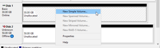
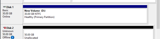
Once the WSFC VMs are configured and started, they should each see the shared LUN under Disk Management from within the OS. Use one of the VMs to partition the disks and format the partitions per the WSFC shared disk requirements. Creating the disk can be performed on only one virtual machine and because it will be set up as a shared disk, the other VMs will detect and partition accordingly. The steps below were done through Disk Management, as shown in Figures 2-5 below.
Validate the Failover Cluster
Now that the VMs are installed and configured, let's run the Failover Cluster validation. This can be run from any VM that will be in the WSFC.
Install the Failover Cluster role on each of the WSFC VMs per the Microsoft documentation.
On one of the VMs, open the Failover Cluster Manager. Select Validate Configuration. This is available from multiple places on the main screen. They all take you to the same wizard.
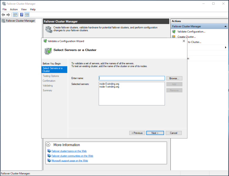
Let's skip the first page, but you can read it first if you want. We need to get to the Select Servers or a Cluster screen (Figure 6).
Enter the computer name for each WSFC node in the Enter name box. Do this one at a time and hit Enter after each. The WSFC server's name and domain will appear under Selected servers. Select Next to continue.

The Testing Options screen allows you to run all the tests or to specify individual tests to run. Let's run all the tests. Select Next. The Confirmation screen appears and shows a summary of the tests to be run. Select Next. See Figure 7.
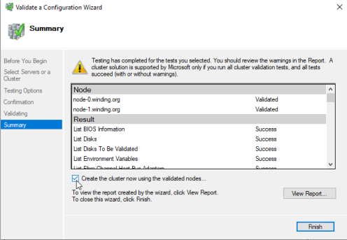
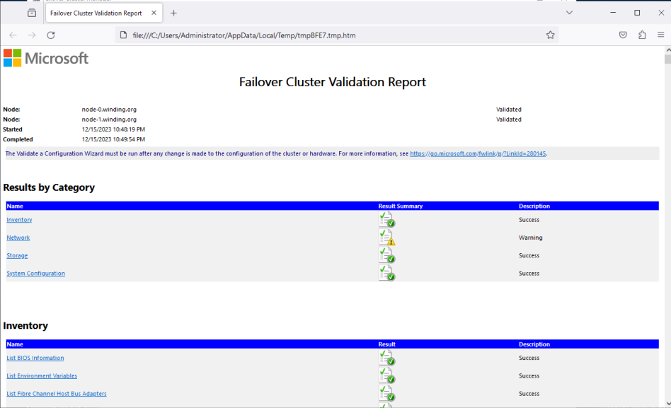
After the tests finish, a Summary screen appears. There is an option to View Report—this opens the validation report in a browser. Select this and let's view the Failover Cluster Validation Report. See Figure 8.
The first section of the report is the Results by Category. The description for the categories should not have any failures. Warnings can be fine, but they should be viewed to make sure the warning is nothing that will cause issues. Failures must be addressed. Figure 9 shows the report.
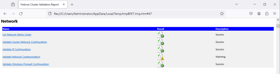
At this point in this learning path, there should only be a Warning for the Network category. Selecting the link next to this category will take you to the Network section of the document (Figure 10). You should see a Warning for Validate Network Communication. Select the Validate Network Communication link to see what is causing this.
The validation should show that the nodes can communicate through a single network path that could be a single point of failure. It should ask that you verify it is highly available. See Figure 11.
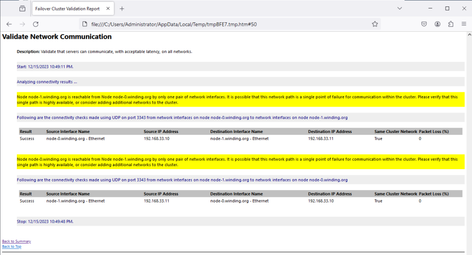
The path should not be a single point of failure, so we should be able to safely ignore the warning. If you want the warning to go away, you can create a second NAD like the first and attach another interface to it. The warning should disappear.
Other issues you may see for networking is that the nodes do not have unique IP addresses. This occurs if the NICs are connected to the Masqueraded Default pod network. To fix this, remove the NIC or connect it to the NAD network.
The results for the Storage category should have ended with a Success. If they did not, they need to be resolved.
None of the Storage tests should have been ignored. If they were, it could be that no disks could be found that needed validation. A cause of this could be the disk was not partitioned and the partition was not formatted correctly as mentioned earlier.
There are a couple things that can be checked if the Validate SCSI-3 Persistent Reservation test fails. First, make sure that errorPolicy is set to report in the VMs YAML as mentioned earlier. If that does not resolve the issue, verify the iSCSI LUN being presented conforms to the SCSI-3 specification and respects Persistent Reservations.
Warning under the System Configuration category is usually a mismatch with Windows updates between the WSFC nodes. All the nodes should have the same software revisions installed.
We can close the Validation Report. The wizards Summary screen has an option to Create the cluster now using the validated nodes.... (See Figure 8 Validate a Configuration Wizard image). Since we had no issues of concern in the validation report, we can select this checkbox and select Finish.
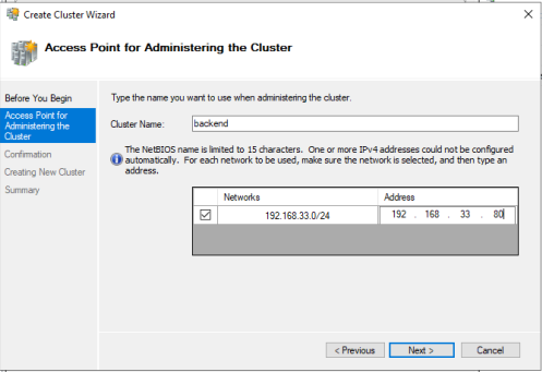
The Create Cluster Wizard appears. Skip to the Access Point for Administration the Cluster screen (Figure 12). Specify a cluster name—we can use "Stars" for the name of our cluster. Specify an IP Address by selecting the Address column. We can use 192.168.33.80 as it’s an unused IP address on the NAD network. Select Next.
The Confirmation screen appears. Select Next to start creating the cluster. A Summary screen appears once the cluster is created. Select Finish.
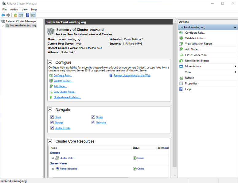
The Failover Cluster Manager now shows information about the Stars Cluster (Figure 13).
Now you have added layers of protection
This learning path has shown how to configure OpenShift Virtual Machines and Windows Servers for Failover Clustering. As shown in the examples above, this can help in a number of ways, such as balancing workloads and safeguarding your valuable data in the event of things like hardware failures or network disruptions.
Congratulations, you are now able to use your storage to further protect your valuable data! Interested in learning more about Virtualization, try this learning path: OpenShift virtualization and application modernization using the Developer Sandbox
